Intro:
The goal of this lab was to get familiarized with the Arduino Uno, a simple microcontroller, and some of its peripherals that will be used throughout the course.
Blinking an LED:
Internal:
Blinking the internal LED started with loading the board with the Arduino example code called “Blink.” In the example code there are two sections: setup() and loop(). Setup() simply contained the code necessary to set the internal LED (LED_BUILTIN) as an output.
Next, the loop() section contained the code responsible for toggling the LED on and off. It was simply one line of code that set the internal LED to high, a one second delay, a line of code that set the LED to low, then another delay.
External:
Blinking an external LED needed only slight modification from the example code. First, a pin needed to be defined to use for the LED. This was done with one short statement at the very top of the program. After that was done, the defined led could be set as an output in the setup() portion of the program instead of the built in LED used for the previous section. The program was finished when the loop() section was updated with the new LED instead of the internal one similarly to the setup() section.
Blinking LED Video
Reading the Potentiometer:
In order to read the value of the potentiometer through a serial port, we needed to use the analog input pins, which are connected to an Analog to Digital Converter (ADC) to provide the chip a 10 bit digital reading. The potentiometer has three pins. The two end pins should be connected to Vdd (High voltage) and ground, and the middle pin should be connected to one of the analog pins. In the code, this can be read by declaring the pin connected to the potentiometer as an input. This pin should then be defined as an analog input, and then an analogRead can be performed in order to find the value. The serial monitor can be opened by clicking the magnifying glass in the arduino IDE, and can be written to with Serial.print().
Mapping the Potentiometer Value:
To an LED:
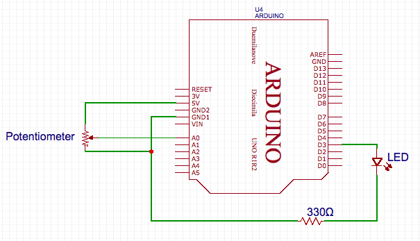
The first stage of the potentiometer mapping was to wire the external circuit appropriately. The circuit consisted of a potentiometer acting as a voltage divider of 5V, an Arduino wired such that the node in the middle of our basic voltage divider ran to an analog input, and an LED wired such that its positive terminal (long leg) was connected to a PWM pin on the Arduino and the cathode had a path to ground (with a 330Ω resistor in series).

LED Wiring Diagram
The potentiometer to LED brightness mapping was handled in software by employing three specific Arduino functions. The first function was analogRead, which allowed the voltage to be read from the middle of the potentiometer voltage divider. The read value was bounded between 0 and 1024 as observed through displaying the read values on the serial monitor. The next function employed was map, which allowed the value read by the analogRead portion to easily be mapped from its original 0 to 1024 range to a 0 to 255 range. A PWM signal only has 8 bits of control, which is why we chose this mapping to synthesize the signal using analogWrite. The aforementioned signal was then used to power the LED creating either a brighter or dimmer appearance based on the duty cycle.
Potentiometer LED Video
To the Servo Motor:
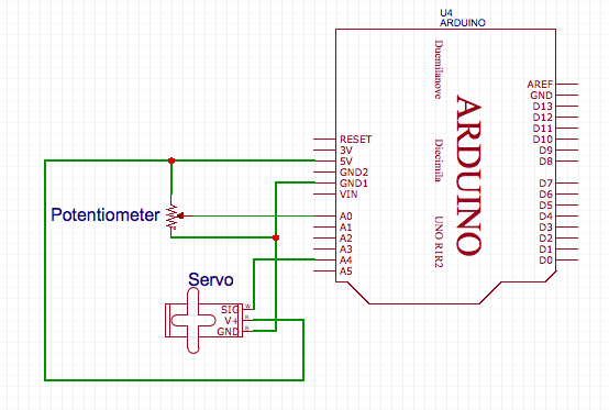
The process of mapping the potentiometer to the LED was the basis for what then became the structure to map the potentiometer to the servo motor. However, several significant changes where made. The first of which was that a new circuit had to be created for the servo motor. The potentiometer and analog input wiring remained the same, but instead of the LED part of the circuitry, a single pin of the Arduino was run to the servo in order to give it rotational information.

Servo Wiring Diagram
The primary software change was that instead of using the PWM signal to drive a circuit component, the Servo library within Arduino was used to command the servo motor’s position. Much the same as before, the potentiometer was read, and the value was mapped, but this time it was set to a range of 0 to 180. The specified range worked as follows: 0 would be full speed rotation of the servo in one direction, 90 would be a complete stop, and 180 would be full speed rotation in the opposite direction. As a part of the Servo library, one pin was declared to be for the servo, and then the only control was to set a value to the pin, specifically the remapped value of our potentiometer.
Potentiometer Servo Video
Assembling Our Robot:
To assemble the chassis of our robot we used the base and two 3D printed structures provided in lab. The 3D printed structures for the wheels are attached to the main chassis base using nuts and bolts, with the servo motors then attached to these side structures. The wheels are then attached to the end of the servo motors. We use a counterweight with a ball bearing on the end to stabilize the base and provide a smooth surface to drive the robot. On the top of the base we place our electrical components including the Arduino and battery pack for motor control.
Driving Our Robot:
We drive our motors using two functions, move_ccw and move_cw, that are based on the previous code used to move the servo except we no longer include the potentiometer readings. Instead, our functions take in a speed from 0 to 90 and the specified servo to move, and then maps this number appropriately. It is important to note that the servo motors are actually facing opposite directions. Thus to move in a straight direction we actually call the function move_ccw for one motor and move_cw for the other. Using this base code we successfully made our robot move in a square pattern. The robot first moved straight, then turned 90 degrees and continued the cycle in a loop. We turn the robot by forcing one motor to rotate while the other remains still. Finally, we tested different delay values that would make the turn approximately 90 degrees before it continued rolling straight.
Robot Tracing a Square Video