Milestones
- Milestone One Line Following and Figure Eight
- Milestone Two Wall Detection and Signal Detection
- Milestone Three Search Algorithm
- Milestone Four Treasure Detection and Evaluation
MILESTONE 1:
Objectives:
One: The robot is able to follow a line and employ self correction to maintain its path.
Two: The robot is able to trace a figure eight on the grid, maintaining its path on a line at all times.
Line Following:
Our robot was able to successfully navigate a line and correct to maintain a straight path.
Basic Line Trace Video
The robot was able to make a strong correction to reach a line and then follow as well.
Strong Correction Video
Figure Eight:
Our robot was able to successfully trace a figure eight on the grid.
Figure Eight Video
Further Explanation:
Implementation:
Two line sensors are used to control the robot’s movement as it attempts to follow the line. They are each attached to digital pins on the Arduino, with one initially starting on the white line and the other starting offset to the right on top of the darker material. We have an initial averaging function that is called in the setup so we can establish threshold values for each sensor. Once we obtain an average over 10 samples, we set threshold variables that we use for the remainder of the program. Within the loop, we use conditionals to check when we need to correct to the left or right based on the running average that we continuously update. With this implementation we successfully followed the white line, but struggled to consistently detect intersections where both sensors were on the white line. For this reason, we decided to adjust the position of the sensors to make our algorithm more robust in the figure eight pattern. However, we had many issues using the digital sensors as it returned fluctuating and negative values that made it hard to establish a threshold. The solution of this problem was that the ISR was gotten rid of entirely because it didn’t work correctly (discussed more later). This implementation traced the line a little more reliably than the last, and turned at the intersections.
In our final implementation we were able to establish stable thresholds and readings from the line sensors, allowing us to consistently correct and turn at intersections. This was achieved with our improved digital pin readings (explained in section below). Within our loop, we have simple conditional statements to check when either threshold is too low, or if both thresholds of the sensors are too low. After slightly adjusting delay times and speeds of the servo motors, we successfully made the robot drive in a figure eight pattern.
Error and Solution to the ISR Sensor Implementation Problem:
Using a digital line sensor created many difficulties in the milestone. The first way the digital sensors were read was using an ISR that was triggered by new input, with each sensor connected to a digital pin. In the ISR, the sensor was read using the built-in micros() function, which measures microseconds since the arduino began running the current program with 4 microsecond precision. When both sensors were on the white line and too close, some type of error was encountered that resulted in negative numbers being read. The way in which the error was corrected was to use a different measurement system after debugging this issue for over an hour with the help of a TA with no improvements.
The improved reading method is to use a function to set the “out” pin to an output, drive it high, then waits 10 microseconds and the pin is changed to an input. The function will return how many microseconds the pin was high for, between 0 and 3000 microseconds, with 4 microsecond precision. It was determined when the sensors were on the line or not by the use of a threshold value. If either sensor was above its threshold value then it would be determined that said sensor was off of the white line. The thresholds were tested using simple if statement conditionals which proved to be more accurate than while loops that were in a previous implementation.
MILESTONE 2:
Objectives:
One: The robot is able to successfully circle an arbitrary set of walls.
Two: The robot is able to avoid other robots in its path.
Three: The robot can line track, avoid walls, and avoid other robots simultaneously.
Wall Detection and Avoidance:
The robot is able to follow walls using thresholding on the solo sensor on the front. Once the robot reaches an intersection it reads the front, wall detecting IR sensor. If the read value is less than the threshold then there is a wall detected and the robot reacts. The react pattern is as follows: if no wall detected if front move forward (after any number of previous turns), if a wall detected turn left and recheck, if there is still a wall then turn around and recheck, and finally if there is still a wall after the 180 degree turn, turn right one last time and return the way it came.
A video of operation can be seen below demonstrating proper line following as well as wall avoidance.
Avoiding Other Robots:
In order to avoid other robots, it was determined that the best algorithm for now would be to simply turn the robot 180 degrees and have it travel the opposite direction it was originally going upon detecting another robot.
Rather than separately demonstrate the robot detection, this was integrated immediately to the overall system demonstrated in a video in the Integrated System section.
Integrated System:
The final integrated system was able to detect other robots and react to them, line trace, as well as avoid walls in the maze. In order to fully display what the action of the robot is two LEDs were implemented as well. The green LED is turned on for the duration that the robot is detecting and avoiding walls. The red LED is on for the duration that the robot is detecting another robot and reacting to the hazard.
Full Detection Video
Further Discussion:
Implementation:
One primary note that is not immediately apparent in implementing this milestone was that the group decided the FFT for robot detection could be run at an interval. To achieve the interval run of the FFT code, a simple count condition was introduced in the loop, such that the variable counted up during the main function. Upon reaching a certain value (20 in this case) the FFT calculation would be triggered and the count reset.
An additional word of caution is that once setting the ADMUX value, there is a finite amount of time that reading the value of the ADC will only give a garbage value. As such, the group's implementation simply read it once to clear the register, delayed for 20 milliseconds, and then read again to receive a valid value.
MILESTONE 3:
Objectives:
One: Robot capable of maze exploration using DFS, BFS, Dijkstra, or A*
Two: The robot is also able to update the GUI
Search Algorithm:
A DFS search algorithm was first started by adjusting the MATLAB example code for BFS to work with ArduinoIDE and then converting it to DFS. Variables for the starting position, array sizes, maze size, direction, and the arrays themselves were declared.
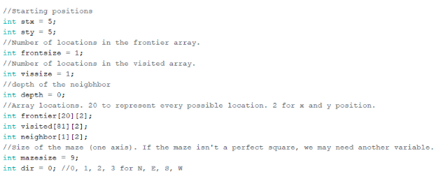
Search Algorithm Setup Code
A loop was created that would continue as long as the frontier array was not empty. A temporary variable popped the first element of the frontier out, and then the size of the frontier was decreased as to create a first in first out (FIFO) buffer.

Search Algorithm Execution Loop Code
Afterwards a group of four if statements (one for each cardinal direction) would move the robot in the desired direction continuously as well as update the arrays appropriately until the robot could no longer move in said direction. At that point, the direction variable would update and the robot would move in a new direction until it could no longer do so.
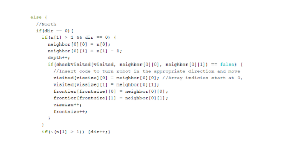
Search Algorithm Conditionals Code
In order to keep the robot from revisiting locations, a function called checkVisited would run each time the robot attempted to move that cycles through the visited array and checks if the proposed new location was already visited.
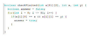
Visited Check Code
Arduino Integration:
In order to integrate the search algorithm with the robot and allow for full functionality, the implementation of the Depth First Search was embedded in the logic when at an intersection. First, the robot adds its current position to the visited array and updates its own coordinates as seen here:
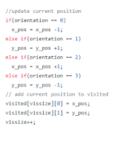
Add to Visited Array Code Snippit
The robot then reads the wall sensors for all directions (Left, Right, and Straight), and depending on the presence of walls or not, the corresponding coordinates are retained in the neighbor array. To calculate the coordinates of each node to add to the neighbor array (given that there is no wall detected), the orientation is taken into account to determine if the robot is facing north, south, east, or west. Either the x or y coordinate is incremented or decremented from the current position based on this orientation and then added. The logic for this can be seen below (NOTE: Orientation is numbered counterclockwise starting at zero for East):
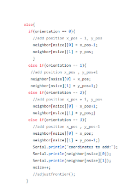
Add to Neighbor Array Code Snippit
Once the neighbor array is updated, the robot then determines a new target index to reach by polling the neighbor array for the most recent entry. If the target index is within one unit of distance (Manhattan Distance used) of the current position, the robot orients to reach the appropriate address by comparing the x and y values of its position, the target position, and its current orientation. However, if the target is greater than one unit away, then the robot begins to backtrack through the visited array until the target is within one intersection. The function that handles this orienting can be seen below:
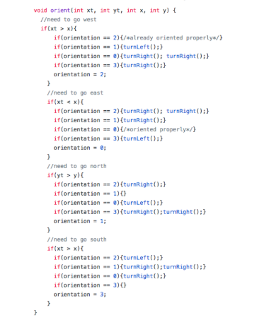
Align Function Code Snippit
After orienting, the robot continues straight until it reaches the next intersection. The outlined process above is repeated continuously until all of the squares have been visited, at which point it has then explored all possible locations. A demonstration of operation can be seen in the videos below:
Maze 1 Exploration
Maze 2 Exploration
MILESTONE 4:
Objectives:
One: Robot which can detect when there are/are not treasures
Two: Robot which can successfully distinguish between red and blue treasures
Three: Robot which can successfully distinguish a square, triangle, and diamond shape
Detecting Treasures and Their Color:
Our method for detecting treasures uses the same method as described in Lab 4.
Color and Treasure Detection
Distinguishing Square, Triangle, and Diamond Shapes:
In order to detect shapes, it is helpful to implement good edge detection, which we do using grayscale filtering. We first attempt to do edge detection using an image convolution that will expose sharp edges in the camera output. To implement this, we compute each output pixel value by applying a convolution matrices to the input image pixels. The particular convolution kernel we attempt to mimic is the following:
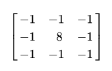
Sobel Filter
To compute the output pixel value, we use a simpler version of the three by three matrix and instead just use the middle row to compute the output. For example, to compute the output values in the 3rd column, we multiply those values by 8 and elementwise subtract the values in the 2nd column and 4th column. The edge values at the first and last column are computed using two columns instead of three. In our implementation, we need to instantiate three different M9K blocks to compute the output values since each block contains only one read port. As we receive pixels from the camera, we write the values to each of the three memory blocks. Thus when we compute the output pixel values we can read from each of the three memory blocks and apply the convolution.
It turns out that this method produces memory issues with the FPGA and would require other methods to compute the convolution in a smart way. Since we would still need to perform processing on the edge exposed image, we instead decide to directly process the output image to achieve some basic functionality first.To distinguish between different shapes, we accumulate color counts at three horizontal lines across the image at different heights. If the color counts are all approximately the same, we will know that the shape is a square. If one color count is significantly different from the other, then we know that the shape is either a diamond or triangle. Our implementation is able to reuse some of the code developed for color detection. For three particular Y_ADDR, we accumulate counts for both the blue and red colors. Then, we use another always block that is triggered by VSYNC to check the count values at the end of every image. In this block, we determine if the absolute value of the count differences between each of the three Y_ADDR is close enough to be a square, otherwise we classify it as a triangle or diamond. The following code demonstrates our method and implementation:

Edge Detection Code Snippit 1
Always block to accumulate color counts for each line at different heights

Edge Detection Code Snippit 2
Difference module to calculate absolute value of differences between line counts for each color.
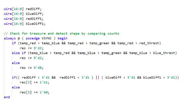
Edge Detection Code Snippit 3
Second part of always block checks difference between line counts and sets res[3] to send shape information to Arduino
The demonstration of treasure detection and color determination by the Arduino was accomplished using two LEDs. A green LED was lit up when a blue treasure was detected (the color mismatch was due to the lab not having any blue LEDs), a red LED is flashed when a red treasure is detected, and finally no LED is lit when there is no treasure detected. The results of the test can be seen in the following video.
Treasure Detection Video