Intro:
The first goal of this lab was to integrate several of the components already created into one platform, namely line sensing, detection of a 660 Hz tone, robot avoidance, and wall detection paired with navigation. The additional step needed in this lab was to now integrate radio transmission to relay data about the maze back to a base station to track progress of maze exploration.
Overview of Hardware and Radio Transmission:
The hardware component of lab was not too intensive as the only true modification since Milestone 2 was to incorporate the tone start. However, the group had this circuit still built from Lab 2 and thus the hardware setup was straight forward. Although, during some down time in lb the circuitry was transitioned from breadboards to protoboards. Once this work was done, it was relatively quick to reintegrate all the components and get them working together again. As for the radio component, we started with some initial tests of the transmitter and receiver to ensure both could communicate with each other. After downloading the Arduino libraries, we changed the addresses of the transmitter and receiver to 0x000000001aLL and 0x000000001bLL. The Arduinos could not supply enough current to power the transmitter and receiver, so instead they are powered directly off the power supply for testing purposes. After this, we were able to successfully transmit the timer samples in the initial example sketch. We then developed a scheme to encode the maze information to transmit from the robot to the base station. This is discussed in the Transmitter section below. Initial tests for the encoding scheme are performed with simulated robot movements that are then decoded at the base station receiver. The receiver uses this information to update the GUI. After this, we integrate everything together with the robot and are able to successfully transmit information about robot position and wall locations in the 2 by 3 maze.
Transmitter:
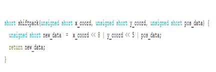
Transmitting started with finding a method of encoding the data we would like to send to the receiver. The data we sended ultimately needed 11 bits. The first 5 bits of the data was information on the position data. For the position data the first four most significant bits represented whether the north, east, south, and west walls (in that order) were present at the location. The least significant bit of the position data represented whether the position was unvisited or had treasure. The remaining bits in the transmitted data were the x and y coordinates of the position. Both coordinates require 3 bits, meaning an 8 by 8 grid can be encoded at most. This can easily be adjusted later for larger mazes. Once the three parts of the data (x_coord, y_coord, and pos_data) are defined, they need to be shifted and packed into the transmitted data. This is accomplished in a separate function. X_coord is shifted by 8, y_coord by 5 and pos_data is left in the least significant bits of the data. After the data is packed it’s sent simply by the function radio.write(). This code is integrated into the entire robot code after individual testing with simulated robot movements.

Data Packaging Code Snippit
Receiver:
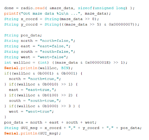
The receiver takes the received data and performs shifts and bit masking to decode the individual x, y coordinates, position data, and wall location. Each of these is needed to create a string that can be pushed to the GUI, which will then update based on the information in the string. To extract the x coordinate we shift the received data by 8 bits to the right, then extract the y coordinate by shifting the data by 8 bits to the right. In order to determine which walls are present, we use bit masking to first extract the bit representing each wall direction and then shift the appropriate number of bits to the right to use in the conditional. We take all the collected data and concatenate it into a string that is sent to the GUI. As shown in the final video, this successfully works together with the actual robot transmitting maze information.

GUI Data Processing Code Snippit
Full Functioning Transmitting and Receiving Wirelessly
Integrating 660 Hz Tone Detection:
The integration of 660Hz starting and IR detection was the same as for the culminating component of Lab 2. In the loop, there is an if statement that checks if a tone has been detected. Until that is the case, the robot only runs FFT code for checking on the 660 Hz tone presence. After a tone has been detected, this if statement is moved past and never re-evaluated. In the remainder of the code, every cycle the robot checks for its positioning via line sensors to stay on track. Every 20 cycles the robot also checks the IR FFT to detect other robots in the maze. Since the microphone FFT and IR FFT use different setups, we initially set everything to work for the microphone, then change it to the setup needed for the IR detection once the tone is detected. Beyond these aspects, the robot also must evaluate the walls around it upon reaching an intersection. The implementation of this functionality was remodeled after Milestone 2, with a full detail of implementation further below. The wall detection programming also directly interfaced with the data packaging and sending for the radio transmission, which also will be discussed in a section below.
Updated Wall Detection Algorithm:
The wall detection only occurs when the robot reaches an intersection. The implementation of the wall detection is via two distance sensors, one mounted on the right hand side of the robot and one mounted on the front. The algorithm is meant to be a right hand wall following pattern with the following logic. If an intersection is reached first check the right wall sensor. If there is no wall present then turn right, but if there is a wall the front wall sensor is checked. If the front sensor senses no wall present, then the robot goes straight. However, if a wall is detected in front then the robot turns to the left and rechecks the front wall sensor. Then, if there is no wall the robot goes straight and if there is a wall then the robot turns left one more time and moves back the direction it came as it has detected a dead end.
Data Storage and Sending:
The final encoding for the maze data on the robot arduino was done as follows. There were two arrays, one of which held the directions: North, South, East, and West. The other held four boolean values. The first array of directions was used in conjunction with an integer index to keep track of the current orientation of the robot with respect to the global, cardinal directions. The boolean array would be set at each intersection based on where there were walls detected for said intersection, such that a value of true in a given index meant that there was a wall at that direction corresponding to the direction at the same index in the direction array. Once all of this was done, a simple conversion was done to take all of this information and send it as one value. The scheme was to have a short that would accumulate values based on wall positions, for example a wall on the north side would add the value 2^4 to the short, one on the south would add 2^3, etc. with the last bit reserved to indicate whether a treasure or other robot was detected.
Final System:
The final system is able to store data about the map that it is currently at and efficiently transmit that data to the base station such that no information is lost and there is no performance degredation. The base station was also able to successfully update the GUI based on the information sent from the traveling robot as it moved about the entire maze. The robot was also able to be triggered based on a 660 Hz starting signal. The culmination of all of these additions can be seen in the final video shown below.