Intro:
The goal of this lab was to create a treasure detection method by using a camera with an FPGA to determine the presence, shape, and color of treasures. These determined results were then to be processed by the Arduino to relay the presence of a treasure and information about it.
FPGA Work
Phase Locked Loop:
The first necessary step in this lab was to create a phase-locked loop to generate a 50 MHz clock for the RAM, a 25 MHz clock for the VGA, and a 24 MHz clock for the camera. This was done following the instructions on the lab handout, and found in Quartus in Tools > IP Catalog.
Displaying an M9K Block:
In order to display these blocks on the screen, we used a large if-else block with three vertical checks and eight horizontal checks, since there are three color options and two of the colors have eight settings. The first row increments the value of the red color by one as the x value grows, the second row increments the red and green colors together, and the last row increments red and green together, and increments the blue color every other block.
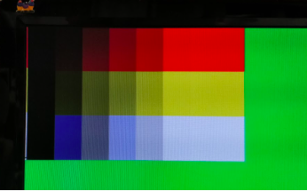
M9K Block Displayed on Screen
Color Bar and Live Camera:
The camera sends the information for a pixel in two bytes in two clock cycles, so we first read both bytes, then sent the data into the downsampler using a data valid bit. The downsampler sets the write enable for the M9K block so that only valid, downsampled data is written, and the HREF line coming out of the camera is used to synchronize the x address of the pixels and when to increment the y address. The y address is only incremented when the HREF signal marks the end of a row of pixels, and the x address is incremented every 2 PCLK cycles and is reset at the end of each row. VSYNC is used to reset both x address and y address at the end of an image frame.
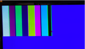
Color Bar Displayed on Screen
Treasure Detection:
The image processor takes in one pixel at a time and determines what the primary color component of that pixel is, and if the primary color component is greater than a set threshold, it will increment a counter for that color. At VSYNC, the counters will be evaluated, and if one color predominates and is greater than a hardcoded threshold, the result will be set to a value corresponding to a color. Using ternary operators, we output on two pins if the color is red or blue and if a treasure is detected or not. Unfortunately, our image processor incorrectly detects treasure, periodically (watch video above). It is much better at detecting colors when there is an actual treasure present, as the GPIO pin is more consistently high with the red treasure in front of the camera. Team arduino will have to use some correction method to correctly detect treasures.
Arduino:
Writing the Camera Registers:
The Arduino side of this lab began with establishing communications to the OV7670 camera module. The means of communication was via I2C, that was connected between the two components as depicted below.
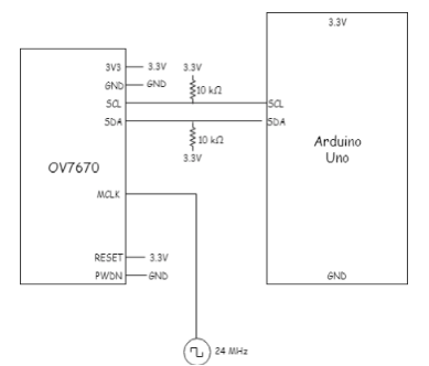
Arduino to Camera Wiring
Once the communications channel was established, the task at hand was to write the appropriate registers on the OV7670 platform to allow for the camera bar testing. After reviewing the datasheet the following register writing was determined to be appropriate.
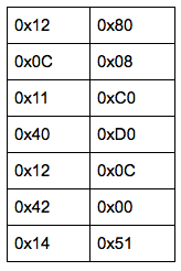
Registers Written on Left and Values on Right
Once we had the values and destination, the Arduino needed to actually write these to the camera. The means of register writing was to call one of the provided functions with the register address and desired value: In order to ensure that the correct values were written to each register, the values are first read at the beginning of operation and displayed on the serial terminal, and then read at the end of operation and displayed on the same terminal. The results of the writing as displayed on the serial terminal can be seen in the following image, exhibiting that each register was updated to the correct values intended by our implementation.
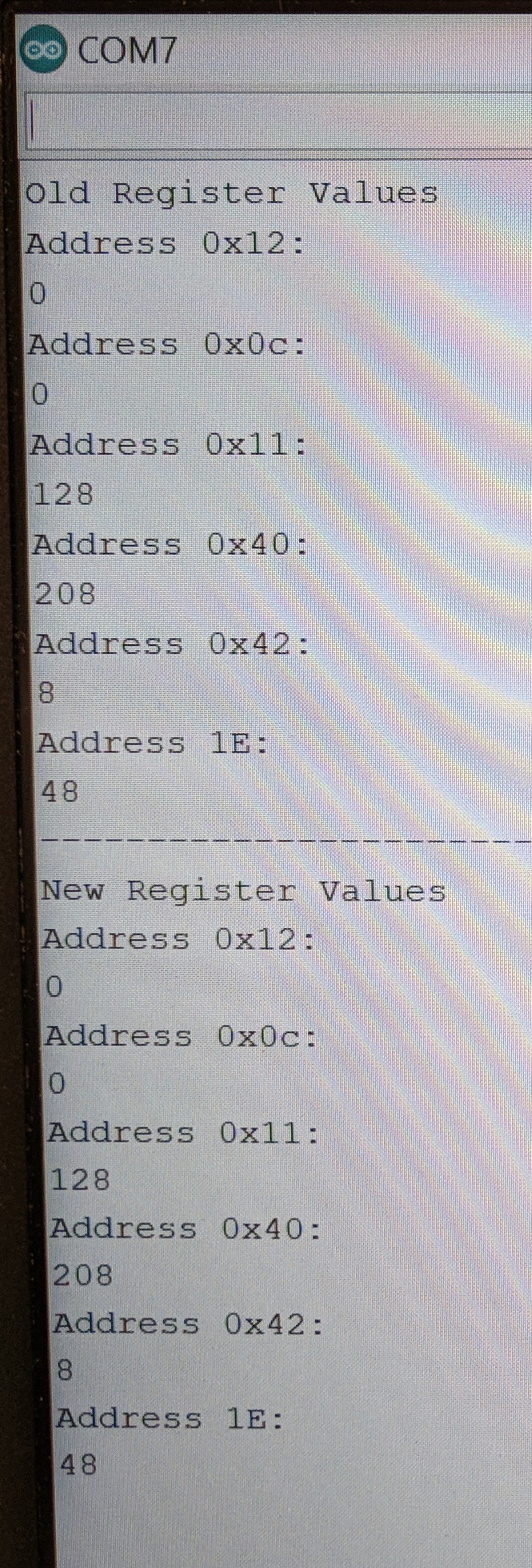
Registers Written on Left and Values on Right
FPGA Communication:
The final aspect of implementation was to create a communication protocol between the Arduino and the FPGA. The general outline of the protocol we developed was a simplistic 5 line parallel communication, one for whether or not a shape was detected (1), one for each shape (4 total), and one for if the color is red or not (5 total) . However, for the lab only two of the lines were necessary: treasure presence and color determination. The FPGA’s pins for these outputs were then wired to two digital pins on the Arduino. Due to random noise, the read could not be done a single time as there was a chance that the read value would be erroneous, thus a different measurement method was devised. Each pin would be read one thousand times, and if the read value was high for greater than 500 of those reads, it was returned as high (nonzero). If not then it was returned as low (0). The function that implemented this can be seen below.
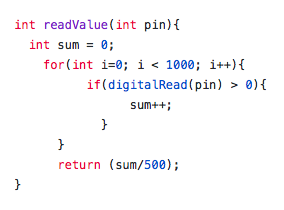
Duty Cycle Read for Treasure Detection
Final Demonstration:
The final demonstration of treasure detection by the Arduino was accomplished using two LEDs. A green LED was lit up when a blue treasure was detected (the color mismatch was due to the lab not having any blue LEDs), a red LED is flashed when a red treasure is detected, and finally no LED is lit when there is no treasure detected. The results of the test can be seen in the following video.
Treasure Detection Video